Adding an external relay output to a FM231 Driveway Alarm
Several years ago, I purchased a Might Mule Driveway Alarm (FM231) which has worked fairly well.

But within the first year, I found that changing the batteries was a pain and that I'd rather have it operate on an AC power source. Nearby the sensor, I had an outlet in the gate operator; so I easily used a wall wort and fed that 5v DC source to the sensor.
A few power surges and then my sensor didn't work any longer. So I ordered another one, but this time I added some protection with a couple of capacitors and a diode on the supply side. Fast forward 3 years later and no issues.
One thing that has been challenging is getting a notification that someone is at the driveway when I'm not in the main entry way of the house (such as in the garden, etc). I've been using Slack as of late to send home automation updates and thought it would be cool to do the same with the driveway alarm.
To do this, the Receiver of the Driveway Alarm needs to be dismantled with the four screws on the bottom.
There is no clean way to get a relay output; since the PIC controller chip that they use seems to have nothing that we can utilize for this. The first method that came to mind would be to use a Peak Detector circuit and use this to drive the output of an emitter follower NPN transistor circuit, which would then drive a relay for our output.
There is a Piezoelectric speaker on the board, but with one caveat, there is a +5VDC signal on the positive pin when there is no sound...more about that later.
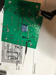
The easiest access is on the back of the board. I directly soldered a 1N4148 diode to this and use some heat shrink tubing to insulate the bare conductor and to bring the cathode side of the diode around to the front of board.
Next, on the front of the board, you need to construct the following circuit/components.
Since the sound going to the piezoelectric speaker is a waveform, we only want the DC component of that signal to charge the 10uF capacitor. The 100K resistor is just a bleed resistor. You could tweak this a bit if you need to change the charge time of the capacitor, but for this use case the 100K works fine.
Next, remember I mentioned that the signal to the piezoelectric speaker has a constant +5vDC to it? This forces us to bias the transistor so that we lower that voltage. I was being lazy and didn't try to calculate this...I just tried various resistor values till I got something that worked correctly. 57K Ohms did the trick.
For the relay, I used one that I had laying around that had contacts rated at 24v DC. You'll want to make sure you use a Flyback diode around the relay coil to protect your circuity.
There is a 12vDC feed off the barrel power connect which is easy access (see red wire in picture below).
For the PeakDetector/Relay circuit this is about it and it works well.
One thing to keep in mind is that the Volume control needs to be at least half way turned up to provide enough voltage to drive the transistor. For my use case, I did not want someone (e.g. my kids) to play around with the volume control and render my tool useless. So a soldered a 1K resistor on the potentiometer / volume control so that I will always have enough voltage/amplitude to drive the relay circuit.
Here is the final circuit in place on the top of the board:
To bring the relay output to the outside of the case, I just used a female RCA jack I had setting on the shelf.
So far this works great! I use the relay output on a set of GPIO pins on a Raspberry Pi (Interrupt driven) and then use that to send an alert via my Slack channel.


No comments:
Post a Comment