Thursday, January 7, 2021

Allstar Raspberry PI USB FOB as a Repeater Controller

For several years I've built home-brewed repeater controllers from custom DIY Arduino controllers to ID-O-MATIC kits, to NHRC controllers. Although these all work as a repeater 'controller', they are rather limited in what they can do.  The NHRC-4 is probably the most versatile of the above listed controllers with native support for a link radio.

But, I wanted the ability to link a repeater over IP and have voice responses, such as time announce or temperature readings triggered through DTMF codes. Plus I wanted to easily customize this with some simple shell scripts or Python code.

So I recently started playing around with the hamvoip.org implementation of the Allstar controller image for Raspberry PI. It really is amazing...I'm surprised I did not play with this earlier!

Bought a handful of cheap CM108 based USB FOBs from Amazon. For around $9 a piece, pretty low cost. I've seen them even cheaper on ebay, especially in larger orders.


 The Raspberry PI 4B is fairly reasonable in price, with the Canakits being on sale from time-to-time for about $70 for the 2GB RAM version (kit includes case, microSD card, heatsinks, Powersupply, HDMI cable, etc.) 


To start with, the USB FOB needs a few components removed. With a Hot Air rework station and a pair of tweezers, its pretty straightforward on removing the two 1/8" jacks, and R6 which is the bias resistor. Probably the hardest part is soldering a connection on pin 48 of the CM108 chip for COS signal and pin 13 for the PTT signal. Some folks  will also solder on a lead to pin 39 for CTCSS. But for my use case, I do the encode/decode on the receiver and transceiver...so I only wanted COS which was enabled on successful decode. So I only used pin 48 & 13 off the chip.

I found the easiest is just to super glue a section of perf board on the back edge of the FOB that I can use that to solder on some of the components along with a 6pin header.

Some folks like to solder on a pigtail lead off the back of the FOB. Personally, since I have a mix of repeaters with different interfaces, I like the header pins so I can swap out to whatever repeater interface I need to use.

 Here is a picture of the finished project.

There are a mix of mods out on the internet. What I ended up doing is using a schottky diode (BAT43) on the COS input to protect from any positive voltage going back to the chip. If you also need CTCSS, you'll have to front end pin 39 with a BAT43 too.

Since I use, in some cases Maxtrac Radios for repeaters, the MIC input on the Maxtrac/Radius radios has DC power for the hand-held Mic. So I put a 10uF cap on each of the audio outputs from the FOB to decouple the DC.

To attenuate the Mic input, a simple divider circuit with an 18K resistor and 1K to ground. That appears to work ok.

For PTT...you have to buffer that output. A simple NPN transistor with the emitter to ground is sufficient. A 4.7K resistor on the base is a good choice.


Here is a diagram with my scribbled notes that you might find useful:


The picture was borrowed from Gary Dion's site (Call sign: N4TXI)

http://www.garydion.com/projects/usb_fob/


Repeater Builder site has some good documents worth referencing too if you are interested in building one yourself.

http://www.repeater-builder.com/projects/fob/startech-fob.html

Overall, I'm pleased with how well this is working for such a small monetary expense.  It works well and with a Linux distribution, it provides a lot of expandable options. Additionally, I have all the GPIO pins available on the Rasberry Pi that I can use to interface with external sensors, controls, etc.


Thursday, September 12, 2019

Just say NO to LMR type cable for Repeater use

Feedlines for Repeater Systems

Recently, I had a discussion with someone regarding what feed-line type to use when it comes to repeater use cases. A lot of folks that start building a repeater for Amateur Radio use are trying to be sensitive to the budget, which I can appreciate. But as one wise person told me many years ago...it only hurts once to buy the correct tool/part.

Many folks look at LMR cable as a great option because the loss is very low for VHF/UHF use cases and its affordable. The issue with duplex operation is that the LMR type cable has an aluminum foil shield with a copper braid. Any dissimilar metals is usually a recipe for disaster. In the case with aluminum, aluminum oxide will form which creates tiny diodes over the length of the cable.  You will get a reaction with the copper and aluminum - and the result is all the same, you will get noise induced when RF power is applied.

Now I remember when I started building repeaters, I thought that this was all folklore and a marketing scheme to get people to buy more expensive feed-line like Heliax. In fact, many commercial radio installation companies use LMR cable for small repeaters at business locations and such. So in years past, when interacting with Elmers that have been doing hilltop repeater work for years, they were saying No to LMR or any other type of cable with dissimilar shields. Well I thought they were just drinking the marketing Kool-Aid. Until I bought a Service Monitor to conduct tests...then I became aware of what noise they've been talking about the whole time.

When doing a 12 dB SINAD test on a repeater/duplexer, you can easily measure the noise induced from an LMR type cable just by small movements of the cable. As a cable ages, this noise increases. This noise causes desense in the receiver and creates wide-band noise that would impact other repeaters at a commercial facility. That is why most commercial repeater sites will NOT allow any installation with this type of cable (I say 'type' because there are other coax types that have similar construction, such as the Belden 9913). Also, any Nickel or chrome plated connectors would also be out of the question, as these can create intermod anywhere along the RF path since they are ferrous metals.

To demonstrate how much noise is induced by even a short LMR240 cable on the antenna output of a duplexer, I put together a short video comparing LMR240 and RG400 into a dummy load. With a 12dB SINAD test on the receiver, you can see that we go from a 'copy-able' signal, to just RF grudge...with small movements of a relatively new cable that is stored indoors. So imagine the noise that is induced on a longer feed-line that goes up a mast or tower and moves (even slightly) in the wind. You're going to get noise and dense...there is no way around it.


Why say no to LMR type cable for repeaters (video)


If a person does not have a Service Monitor, or a way to test receiver noise, then its pretty hard to quantify this noise. But several years ago, when my radio hobby became more serious (I was building and installing repeaters and building RF PAs) a Service Monitor was a must. Once I put a repeater on the bench to test, then my eyes were fully opened to how the Old-timers doing this for so long were preaching of this very fact of not using LMR cable for this application.


Now for simplex operation LMR cable works great. It has a lot of great characteristics for this use case: its low cost, low loss, can handle relatively high power and easily available for purchase.  But for Duplex operation, its imperative to use the right cable, such as Heliax  LD4-50a, or whatever  corrugated version is appropriate for your power and length.

For more in-depth details on Repeater construction, the repeater-builder.com site has a wealth of information. 


Thursday, May 16, 2019

Adding a relay output from a Mighty Mule Driveway Alarm for Raspberry Pi or Arduino, etc.


Adding an external relay output to a FM231 Driveway Alarm

Several years ago, I purchased a Might Mule Driveway Alarm (FM231) which has worked fairly well.

Wireless Driveway Alarm System

But within the first year, I found that changing the batteries was a pain and that I'd rather have it operate on an AC power source. Nearby the sensor, I had an outlet in the gate operator; so I easily used a wall wort and fed that 5v DC source to the sensor.

A few power surges and then my sensor didn't work any longer. So I ordered another one, but this time I added some protection with a couple of capacitors and a diode on the supply side. Fast forward 3 years later and no issues.

One thing that has been challenging is getting a notification that someone is at the driveway when I'm not in the main entry way of the house (such as in the garden, etc). I've been using Slack as of late to send home automation updates and thought it would be cool to do the same with the driveway alarm.

To do this, the Receiver of the Driveway Alarm needs to be dismantled with the four screws on the bottom.

There is no clean way to get a relay output; since the PIC controller chip that they use seems to have nothing that we can utilize for this. The first method that came to mind would be to use a Peak Detector circuit and use this to drive the output of an emitter follower NPN transistor circuit, which would then drive a relay for our output.

There is a Piezoelectric  speaker on the board, but with one caveat, there is a +5VDC signal on the positive pin when there is no sound...more about that later.

The easiest access is on the back of the board. I directly soldered a 1N4148 diode to this and use some heat shrink tubing to insulate the bare conductor and to bring the cathode side of the diode around to the front of board.


Next, on the front of the board, you need to construct the following circuit/components.


Since the sound going to the piezoelectric speaker is a waveform, we only want the DC component of that signal to charge the 10uF capacitor. The 100K resistor is just a bleed resistor.  You could tweak this a bit if you need to change the charge time of the capacitor, but for this use case the 100K works fine.


Next, remember I mentioned that the signal to the piezoelectric speaker has a constant +5vDC to it? This forces us to bias the transistor  so that we lower that voltage. I was being lazy and didn't try to calculate this...I just tried various resistor values till I got something that worked correctly. 57K Ohms did the trick.

For the relay, I used one that I had laying around that had contacts rated at 24v DC. You'll want to make sure you use a Flyback diode around the relay coil to protect your circuity.

There is a 12vDC feed off the barrel power connect which is easy access (see red wire in picture below).

For the PeakDetector/Relay circuit this is about it and it works well.

One thing to keep in mind is that the Volume control needs to be at least half way turned up to provide enough voltage to drive the transistor. For my use case, I did not want someone (e.g. my kids) to play around with the volume control and render my tool useless. So a soldered a 1K resistor on the potentiometer / volume control so that I will always have enough voltage/amplitude to drive the relay circuit.


Here is the final circuit in place on the top of the board:


To bring the relay output to the outside of the case, I just used a female RCA jack I had setting on the shelf.


So far this works great! I use the relay output on a set of GPIO pins on a Raspberry Pi (Interrupt driven) and then use that to send an alert via my Slack channel.


Saturday, March 16, 2019

UV-5R COR Signal

How to Get a UV-5R COR Signal

A while back, a discussion on a radio forum came about on how would someone get a COR signal out of a UV-5R for the possibility of using it as a portable repeater receiver. Now I will not debate that the UV-5R is not the best receiver to use for this as it has a wide open front end and subject to overload and desense. But ignoring that issue and trying to solve the answer to question lead me to split one open and look inside. With the help of a schematic and a DMM , an easy point to get COR can be achieved.


Looking at the schematic diagram, the TDA2822 opamp that is used for the speaker, only gets power when the PL/DCS is unlocked. Otherwise, the TDA has no power. Therefore, its a great place to use to get a COR signal. I've tested this and I'm using this currently attached to a high impedance input on an Arduino I'm using as a controller.

You can see the NPN transistor (Q19) that is providing the power to the op amp. This only comes on when the PL/DCS code opens.

One other note, the surface mount op amp is very,very sensitive to heat. So if you do solder on that pin 2, be very careful you don't overheat it otherwise you'll destroy that chip.


Here is the quick video on where you can get a COR signal if you really wanted to use a UV-5R for this purpose.

https://youtu.be/ejhxLleNXHw

Tuesday, March 12, 2019

Transmitter Spectral Purity - BTECH GMRS1

BTECH GMRS-V1 HT

In a follow-up to my previous post on the spectral purity of several transmitters, I decided to bench test the newer BTECH GMRS-V1.

The BTECH GMRS-V1 is basically a UV-82 rebranded and with software to lock down the HT so that its Part 95a compliant (such as you can not change the front control to VFO mode like on other Baofeng / BTECH radios).

It has an FCC ID of 2AGND-GMRS-V1. If you are interested in all the FCC details take a look here: https://fccid.io/2AGND-GMRS-V1

Overall, it looks to be a decent radio as I've used the UV-82's for sometime now and they are a better design than the older UV-5R.

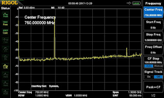
Please note the SA output for this radio on one of the GMRS channels:


As you can see, this radio is much cleaner then the UV-5R and would be expected to be such for Part95 operation.

All the UV-82 accessories work on this radio too.

To date, the BTECH GMRS-V1 is probably the most cost effective GMRS repeater ready radio as it also provides VHF/UHF scanning/RX mode of the range of a typical UV-82. As I use this radio more, I'll post updates.

Thursday, December 28, 2017

Transmitter Spectral Purity - Baofeng, Wouxun, Yaesu


This will be my first post on blogger.com. I've posted on various forums in the past, but I think a consolidated location to post various findings would be helpful, at least for me to go back and reference. Additionally, if new data is found, it would be a convenient place to add an addendum. 

Spectral Purity of various Ham Radio Transmitters


I thought I'd post some findings related to the spectral output of several models of Amateur Radio equipment. What spawned this was I happened to run across some articles about people using Baofeng UV-5R HTs for portable repeater use (basically putting them in an ammo box). A similar site referenced a related article in QST about the Baofengs dirty transmitters (at least on some of the DUTs).

So this encouraged me to put some transmitters on the bench and test with a Spectrum Analyzer  to see which ones have a 'measurable' amount of dirt / harmonics transmitted. Some notes on the test and the attached pictures:

1. I used a 30dB ISO tee  to sample the output with an additional 10dB attenuator (total 40dB attenuation) to get well below my safe max input of 20dBm. 50Ohm dummy load was obviously used to terminate the ISO-tee through connection.

2. All HT's were set at the high setting. On the other hand the Yeasu FT-8900R was set at MID2 which is 10watts.

3. I was not intending to do FCC Part §97.307 compliance testing; The intent was just to check for 'grass' (spurious output) and see a side-by-side comparison with the same test setup. The findings seemed to be inline with what others have seen.


4. Spectrum Analyzer was set to full Span.

The following radios were tested at both 140Mhz and at 440Mhz:
  • Baofeng UV-5R
  • Baofeng UV-82C (Supposed to be Part 90 compliant)
  • Baofeng BF-F8HP
  • Wouxun KG-UV8D
  • Wouxun KG-UV9D
  • Yaesu FT-8900R


Here are the screen shots of Spectrum Analyzer for each model.
UV-5R @ 140Mhz
 UV-5R @ 440Mhz


Baofeng UV-82C @ 140Mhz

Baofeng UV-82C @ 440Mhz


Baofeng BF-F8HP @ 140Mhz

Baofeng BF-F8HP @ 440Mhz


Wouxun KG-UV8D @ 140Mhz
 
Wouxun KG-UV8D @ 440Mhz


Wouxun KG-UV9D @ 140Mhz
 
Wouxun KG-UV9D @ 440Mhz


Yaesu FT-8900R @ 140Mhz
Yaesu FT-8900R @ 440Mhz


Summary:
The Yaesu was clean on both 2m and 70cm band. Any noise was close to the noise floor. Additionally, both Wouxun's DUTs were clean. 

But the Baofeng did produce some spurious emissions that were 'measurable'. Worse on 2m than 70cm. The UV-82c was the cleanest on 70cm of all the Baofeng models tested.


The output does show which radios have spurious transmissions and which ones do not.